What Is a Fiber Laser Cutting Machine?

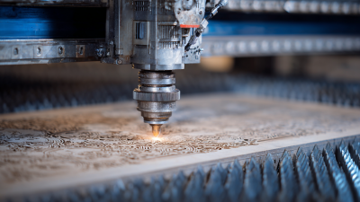
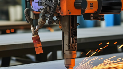
A Fiber Laser Cutting Machine uses a concentrated beam of light to cut or mark sheet material. The beam is guided through a fiber-optic system and focused onto a small point. This focused energy heats the material, while an assist gas helps clear molten material from the cut. The result can be a narrow, clean edge. The exact finish depends on the machine, material, settings, and operator.

These machines are commonly used to process metals such as stainless steel, mild steel, and aluminum. A workshop might use one to cut brackets from a flat sheet, producing repeatable shapes with little material left between parts. Yet “fast” does not always mean “better.” Power, cutting speed, focus position, sheet thickness, and gas pressure must work together. A poor setting can leave rough edges, excess heat marks, or incomplete cuts. That matters.

When comparing machines, buyers should look beyond the headline power rating. Bed size, control software, service support, maintenance needs, and operator training all affect daily performance. Fiber lasers also have material limits; they are not the best tool for every non-metallic sheet or every production task. Requirements vary by shop. A practical evaluation starts with real sample parts and the materials a business actually plans to cut. It is also sensible to confirm specifications with the manufacturer and test the machine under suitable operating conditions. The technology is capable, but results still depend on careful setup—and sometimes the first cut teaches more than the brochure.
What Is a Fiber Laser Cutting Machine?

What a Fiber Laser Cutting Machine Is

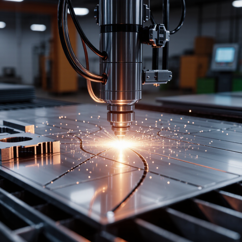
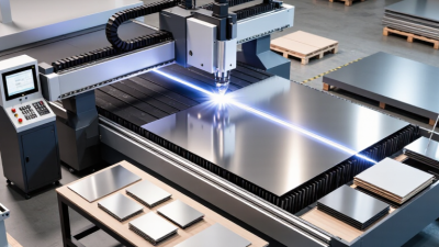
A fiber laser cutting machine uses a solid-state laser source to create a concentrated beam, then guides it through an optical fiber to a cutting head. A focusing lens concentrates the near-infrared light into a tiny spot on the material. Heat melts or vaporizes the metal, while assist gas clears material from the cut. The machine’s computer-controlled axes follow a programmed path across sheet or tube. That is the basic idea.

The name can make the machine sound simpler than it is. Cutting results depend on laser power, focus position, travel speed, material, and gas pressure. A small change in focus can leave rough edges or excess heat marks. The wavelength is typically around 1.06 micrometers, which is readily absorbed by many metals.

Laser Focus World’s 2024 global market review valued the wider laser industry at about US$20.5 billion in 2023; that figure includes many laser applications, not cutting machines alone. It signals broad industrial use, but it does not tell you how a particular machine will cut.

In practice, operators still test settings on the actual material and thickness. A clean-looking specification sheet is not a cutting test.
How Fiber Laser Cutting Machines Work

What Is a Fiber Laser Cutting Machine?

How Fiber Laser Cutting Machines Work

A fiber laser cutting machine converts electrical energy into a concentrated beam of light. Pump diodes send energy into a special optical fiber, where the light is amplified. The fiber’s structure guides the beam toward the cutting head. Inside the head, lenses focus it into a tiny spot on the material. That is the core.

At the focal point, intense heat melts or vaporizes a narrow path through the metal. A computer-controlled motion system moves the head or workpiece along the programmed shape. Assist gas flows through the nozzle, clearing molten material from the cut. Oxygen can support cutting through an exothermic reaction, while nitrogen often helps produce a cleaner edge on suitable materials. The right choice depends on the metal and the desired finish.

Small details matter. Focus position, nozzle distance, gas pressure, cutting speed, and material thickness all affect the result. A bright spark does not always mean a clean cut; rough edges can signal that settings need attention. Operators usually test and adjust parameters for each job, rather than relying on one universal recipe. Reflective metals also require equipment and procedures designed to manage reflected laser energy safely.

The Main Components of a Fiber Laser Cutting Machine

What Is a Fiber Laser Cutting Machine?

The Main Components of a Fiber Laser Cutting Machine

A fiber laser cutting machine turns electrical energy into a concentrated light beam, then guides it through a cutting head onto metal sheet. Its core components work as one system; a weak link can leave rough edges or inconsistent cuts. Small parts matter.

The laser source generates the beam, commonly using ytterbium-doped fiber. Fraunhofer Institute for Laser Technology technical materials place typical ytterbium fiber-laser wavelengths around 1.03–1.08 micrometers. A delivery fiber carries that beam to the cutting head, where collimating and focusing optics shape it into a tiny, intense spot. The nozzle directs assist gas around the beam to clear molten material. The gas choice and pressure affect edge quality, so operators often adjust them for material and thickness.

The motion system moves the head or worktable along programmed paths, while CNC controls coordinate position, speed, and laser output. A chiller stabilizes source and optics temperatures; extraction equipment removes smoke and fine particles. Alignment is unforgiving. Even a clean lens can produce poor results if the nozzle is off-center. One detail is easy to overlook: maintenance records matter as much as the machine’s headline power rating. A simple log of lens cleaning, nozzle changes, and cooling alarms helps explain sudden changes in cut quality.

What Is a Fiber Laser Cutting Machine? - The Main Components of a Fiber Laser Cutting Machine

Main Component What It Does Typical Elements Key Operating Considerations
Fiber laser source Generates the high-intensity laser beam used to melt or vaporize material along the cutting path. Laser diodes, gain fiber, resonator, power supply, and control electronics Output power and beam quality affect cutting capacity and speed. Keep the source within its specified temperature and maintenance conditions.
Beam-delivery fiber Transfers the laser beam from the source to the cutting head while maintaining a flexible optical path. Protected optical fiber, connectors, and routing or strain-relief hardware Observe the specified bend radius and protect connectors from dust, impact, and contamination.
Cutting head and optics Collimates and focuses the beam onto the workpiece; the nozzle directs assist gas toward the cutting zone. Collimating lens, focusing lens, protective window, nozzle, and optical housing Lens condition, focus position, nozzle alignment, and standoff distance influence cut quality. Optical parts require clean handling.
Height-sensing system Maintains the cutting head at the programmed distance above the material surface as the machine moves. Capacitive sensor, height controller, and sensing connection to the nozzle Correct calibration and a clean, undamaged nozzle help maintain stable height control, especially on uneven sheet.
CNC controller Interprets the cutting program and coordinates motion, laser output, gas control, and other machine functions. Industrial computer or controller, operator interface, motion software, and input/output modules Program settings must match the material, thickness, focus, gas, and process parameters used for the job.
Motion system Moves the cutting head and workpiece relative to one another along the programmed cutting path. Servo motors, drives, linear guides, racks or ball screws, and position feedback devices Mechanical alignment, lubrication, and secure mounting help maintain positioning accuracy and repeatability.
Machine bed and frame Supports the workpiece and moving assemblies while resisting cutting forces and vibration. Structural frame, slat supports, worktable, and machine enclosure or guarding A stable, level installation and routine removal of cutting slag help protect the table and maintain reliable operation.
Assist-gas system Supplies gas through the cutting nozzle to help eject molten material and influence the cut edge. Gas source, regulator, valves, filters, pressure sensors, and delivery lines Gas type and pressure depend on the material and cutting process. Use suitable regulators and follow safe cylinder or supply-line practices.
Cooling system Removes heat from components such as the laser source and cutting-head optics, as specified by the machine design. Chiller, coolant circuit, pumps, filters, temperature sensors, and flow monitoring Maintain the specified coolant condition, temperature, and flow. Check for leaks and follow the equipment manufacturer's service schedule.
Fume extraction and filtration Captures smoke, dust, and particles produced during cutting to help maintain a cleaner work area. Extraction ducting, worktable zones, fan, and suitable filtration unit Use extraction appropriate to the material being cut and inspect filters and ducts regularly. Some materials require additional controls.
Electrical cabinet and safety systems Distributes electrical power and supports machine interlocks and protective functions. Power components, circuit protection, wiring, emergency stops, door interlocks, and warning indicators Keep access panels closed during operation and have electrical inspection or repair performed by qualified personnel.

Materials and Applications of Fiber Laser Cutting

What Is a Fiber Laser Cutting Machine?
Materials and Applications of Fiber Laser Cutting

A fiber laser cutting machine focuses light through an optical fiber to cut conductive materials. Common choices include carbon steel, stainless steel, aluminum, copper, and brass. It is especially useful for sheet-metal parts with detailed contours, narrow slots, and repeatable dimensions. World Steel Association’s World Steel in Figures 2024 reports 1,888 million tonnes of crude steel production in 2023. The International Aluminium Institute records 70.6 million tonnes of primary aluminum production that year. These figures describe material production, not laser-cutting demand, but they show the scale of industries that process these metals. Reflective metals need careful parameter selection. Power, assist gas, thickness, and focus all affect edge quality.

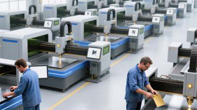
Applications range from automotive brackets and appliance panels to electrical enclosures, machine guards, and architectural parts. A production shop might cut a stainless-steel enclosure panel, then switch to thin aluminum components on the same system. Yet the machine is not equally suited to every job. Highly reflective copper can require more careful setup, while thick sections may be slower or less economical than other cutting methods. A cut edge can still disappoint. Burrs, heat marks, and dimensional drift may appear when settings or material conditions change. Operators should test representative stock before committing to a production run, and verify tolerances against the finished part’s actual requirements.

Approximate Melting Points of Common Fiber-Laser-Cut Metals

Fiber lasers are commonly used to cut carbon steel, stainless steel, aluminum, copper, and brass. The chart compares representative melting points; actual values vary by alloy. Cutting performance also depends on thickness, laser power, material reflectivity, and assist gas.

Key Benefits and Limitations of Fiber Laser Cutting Machines

A fiber laser cutting machine directs a concentrated beam through a flexible optical fiber to cut metal sheet or plate. Its high energy density can produce narrow kerfs and clean edges, often with less mechanical force than traditional cutting methods. For a shop processing stainless steel or aluminum, fast changes between parts can reduce setup time. The result is precise. Yet performance depends on material, thickness, assist gas, and settings.

These machines can cut many conductive metals efficiently, and their solid-state design generally needs less routine maintenance than some older laser systems. A stable beam also supports repeatable production when operators keep lenses clean and calibrate the cutting head. Small details matter: a dusty protective window or incorrect focus can leave rough edges or dross beneath the part. Not always obvious.

There are limits. Purchase and installation costs can be substantial, and very thick plate may require slower cutting or different equipment. Reflective metals need suitable machine design and operating procedures; they are not automatically simple to process. Extraction systems must also capture fumes and fine particles. A neat cut on a sample plate can still mislead. Before choosing a machine, compare real production samples, energy use, service requirements, and the thickness range your work actually demands.