© 2025 Messer Cutting Systems, Inc.

Choosing the right Thermocouple Module starts with the measurement, not the product label. Identify the thermocouple type, operating temperature range, and number of measurement points. A K-type probe may suit a broad temperature range, while other types can better match particular materials or conditions. Compatibility matters. A module designed for the wrong sensor type can produce readings that look plausible but are inaccurate.
Check the module’s stated accuracy, resolution, and cold-junction compensation method. Then consider the installation. A control cabinet near motors may need stronger noise protection or channel isolation than a quiet laboratory bench. Details matter. Also confirm the available interface, supply voltage, wiring terminals, and software support. A long cable run can affect signal quality, so review the manufacturer’s wiring guidance before committing.
In practice, a datasheet comparison is useful, but it does not answer every question. Ask how the module behaves across your actual temperature range and whether calibration procedures fit your maintenance routine. Not always obvious. A small mismatch in connector type or input configuration can slow commissioning. Leave room for that possibility. The best choice balances measurement needs, site conditions, integration, and future service—not just a low purchase price. If specifications seem unclear, verify them with the manufacturer before installation.
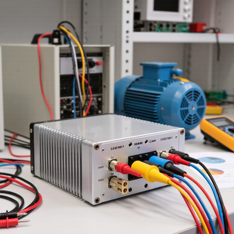
Before choosing a thermocouple module, define the temperatures it must measure in normal operation and during brief peaks. A furnace set to 700°C may experience hotter door-side surfaces, while a cold-start process may need reliable readings below room temperature. Record the full expected range, including startup, shutdown, and abnormal-but-plausible conditions. That detail matters.
Next, set an acceptable measurement error. A display that reads within 2°C may suit general equipment monitoring, but a tighter process may need better accuracy across the entire range. Check the thermocouple type, extension-wire compatibility, and cold-junction compensation requirements. These details affect the reading. Also note how quickly temperatures change; a slow sampling rate can miss short fluctuations, even when the sensor responds quickly.
Consider the installation, too. Count the measurement points, note cable lengths, and check for electrical noise from nearby motors or heaters. Decide whether channels need isolation, and whether the module must report sensor faults such as an open circuit. Small errors add up. In practice, teams sometimes specify the ideal operating range but forget maintenance access or future sensor replacement. That oversight is easy to make. Write down the assumptions, then confirm them against the actual installation before comparing modules.
How to Choose the Right Thermocouple Module? - Define the Temperature Measurement Requirements
| Requirement | What to Define | Example or Selection Guidance | Why It Matters for the Module |
|---|---|---|---|
| Temperature range | Minimum and maximum process temperatures, including expected excursions. | A furnace may need to measure from 700°C to 1,100°C; a chilled process may require measurements below 0°C. | Confirm that the thermocouple type, probe, input range, and module measurement range all cover the full operating range. |
| Thermocouple type | Specify the sensor type and matching extension or compensation cable. | Type K: −200°C to 1,372°C; Type J: −210°C to 1,200°C; Type T: −200°C to 400°C; Type N: −200°C to 1,300°C; Types R and S: 0°C to 1,768°C. | The module must support the selected thermocouple type and its reference tables. These are standardized ranges, not a guarantee of probe suitability at every temperature. |
| Measurement accuracy | Set the allowable error for the complete measurement chain. | For a process limit of ±2°C, account for sensor tolerance, module error, cold-junction compensation, wiring, and installation effects. | Compare total system uncertainty—not just the module’s stated accuracy—with the process tolerance. |
| Resolution and display precision | Define the smallest temperature change that must be detected. | A display step of 0.1°C may be useful for trending, but it does not by itself mean the measurement is accurate to 0.1°C. | Check module resolution, noise performance, and accuracy as separate specifications. |
| Number of measurement points | Count current sensors and planned expansion points. | For 12 thermocouples, consider a module with at least 12 compatible inputs or multiple modules with sufficient capacity. | Verify channel count, channel-to-channel isolation, and whether channels can use different thermocouple types. |
| Cold-junction compensation | Determine how the reference junction will be measured or maintained. | Most direct-connected thermocouple systems use cold-junction compensation at the module terminals; external reference-junction arrangements are also possible. | Check the compensation method, specified performance, terminal temperature limits, and whether the terminals require a stable thermal environment. |
| Electrical environment | Identify nearby motors, drives, switching equipment, ground differences, and cable routes. | Use properly shielded, thermocouple-compatible wiring and separate signal cables from high-noise power wiring where practical. | Consider input filtering, isolation, grounding instructions, and noise immunity to reduce measurement interference. |
| Response time and filtering | Define how quickly the system must report a changing temperature. | A slowly changing tank may tolerate a longer filter; a fast process may require a quicker update and a suitable probe construction. | Module conversion time, configured filtering, scan rate, and probe response all affect the overall response. |
| Installation and environment | Specify ambient temperature, vibration, moisture, mounting location, and available space. | Check whether the module will be installed in a control cabinet and whether the probe needs a protective sheath or thermowell. | Ensure module environmental ratings and sensor construction suit the installation; the module’s ambient limits are separate from the thermocouple’s process-temperature range. |
| System interface | Identify the controller, I/O platform, communication method, and required data format. | Confirm compatible hardware, configuration software, signal scaling, diagnostics, and any required fieldbus or network connection. | A Thermocouple Input Module must integrate with the control system and expose temperature values and fault information as required. |
Selection check: Before ordering, confirm thermocouple type, measurement range, total accuracy, channel count, cold-junction compensation, isolation, wiring requirements, environmental ratings, and controller compatibility against the module documentation.